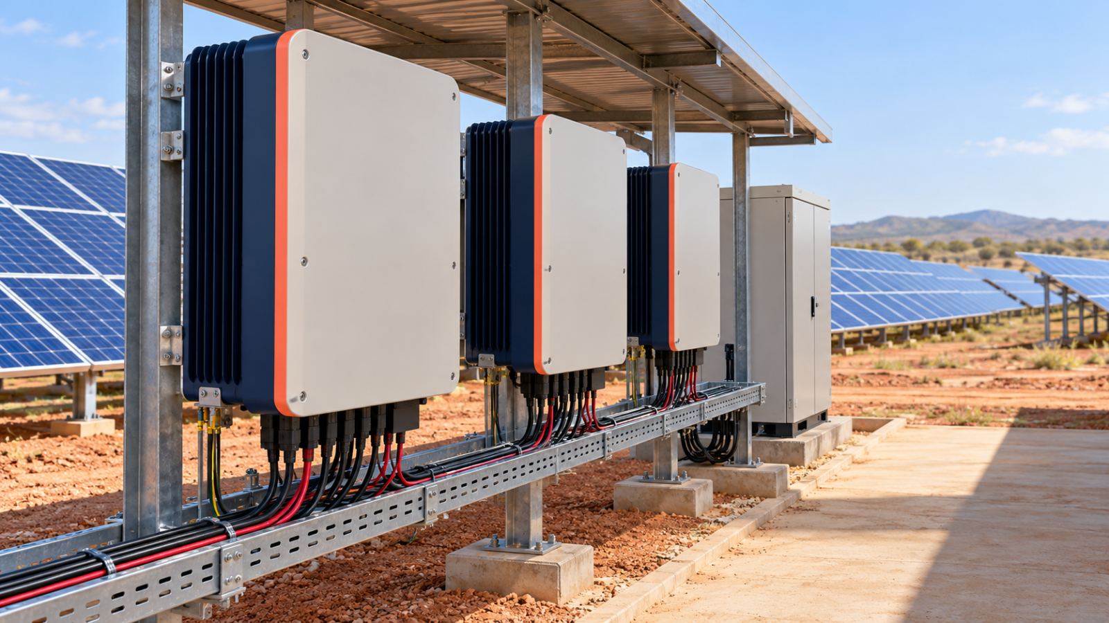
What an inverter does beyond DC-to-AC conversion — synchronisation, protection, monitoring and grid support
The inverter converts direct current (DC) from the solar modules to alternating current (AC) for site loads or export. During grid-connected operation, it synchronises its output with the grid’s voltage waveform and frequency, monitoring conditions at the connection.
Simplified DC-coupled hybrid arrangement. The battery connects to the inverter’s DC side, with isolation equipment separating backup loads from the utility grid during an outage.
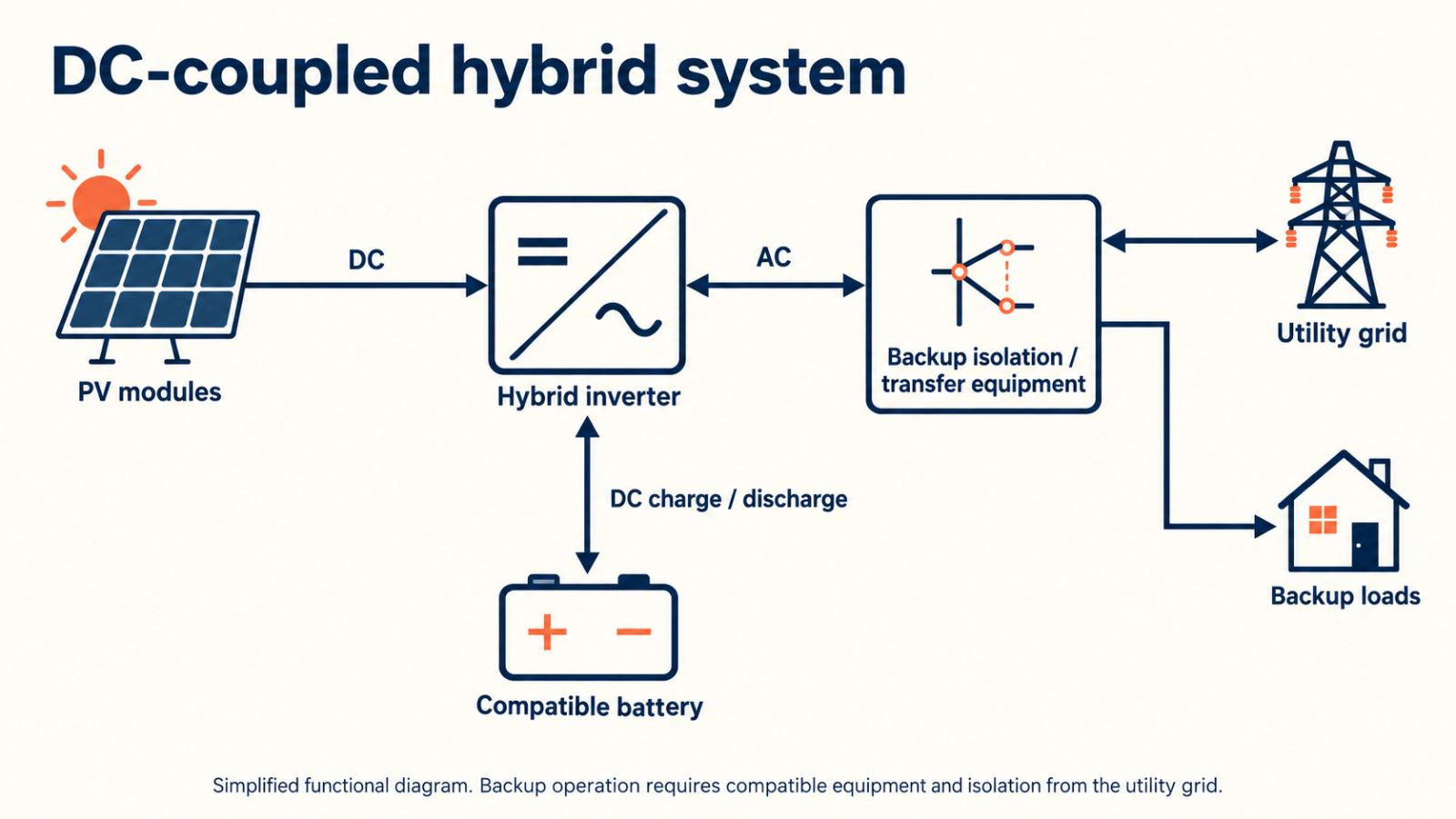
During a grid outage, anti-islanding protection disconnects the inverter from the utility network. To continue supplying site loads, the installation requires a backup-capable configuration with suitable switching equipment to isolate the backup circuit from the grid.
Production records and fault logs help maintenance teams trace reduced output. Depending on the model, the inverter also supports grid voltage through reactive-power control under local connection rules.
For the proposed inverter, check the datasheet for supported grid-control functions and the installation manual for permitted settings. Its IEC 62109 documentation addresses a separate procurement check: safety against hazards such as electric shock and fire.
MPPT explained — the I–V curve, the maximum power point, and why several MPPT inputs matter under shading or mixed orientations
An array delivers different amounts of power depending on its operating voltage and current. The I–V curve plots current against voltage. Multiplying the two values at successive points produces the P–V curve, with its peak marking the maximum power point:
MPPT, maximum power point tracking, adjusts the array’s operating voltage to seek this peak as sunlight and cell temperature vary.
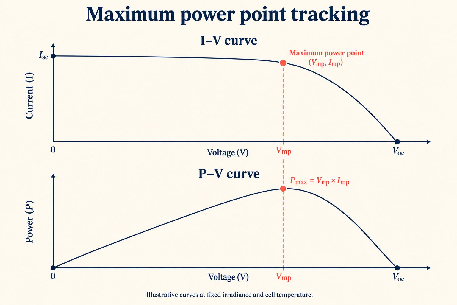
The maximum power point pairs operating voltage Vmp with current Imp. Their product marks the peak of the P–V curve.
On a roof with east-facing and west-facing sections, independent MPPT channels let the two groups operate at separate voltages. This separation also helps manage groups with different shading exposure. Within a shaded group, several peaks sometimes develop on the P–V curve, prompting suitable shade-management algorithms to search for the highest available peak. Tracking improves power extraction from the remaining sunlight; shading still reduces production.
Separate connections do not always mean separate tracking: several string inputs might share one MPPT channel, operating at a common voltage. The manufacturer’s connection requirements specify the permitted string groupings and electrical limits, forming the basis for assigning roof sections to independent channels.
String, central, micro, optimisers, hybrid — choosing by project type and scale
With string inverters, conversion from DC to AC is distributed among units serving groups of module strings. A central inverter collects DC from a large array at a conversion station. This affects the production lost during a unit outage: a distributed arrangement limits the affected capacity, while a central unit concentrates more capacity at one point. Repair access and replacement stock influence how long production remains interrupted.
Microinverters bring DC-to-AC conversion to individual modules. Power optimisers regulate DC output at module level, with a compatible inverter performing AC conversion. Some commercial optimisers connect to two modules, so the control arrangement depends on the product.
| Architecture | Typical application | Strengths | Points to examine |
|---|---|---|---|
| String | C&I roofs; ground-mount | Distributed conversion; multiple MPPT channels on suitable models | Unit count and replacement access |
| Central | Utility-scale plants | Aggregated conversion; potential economies of scale | Capacity affected by outages and site-service arrangements |
| Microinverters | Complex roofs | Module-level conversion and tracking | Cost and rooftop replacement access |
| Optimisers | Roofs with mismatch or shading | Module-level DC control and monitoring | Inverter compatibility and additional rooftop components |
| Hybrid | Storage and backup projects | Coordinated PV and battery operation | Battery compatibility and backup power limits |
Hybrid refers to battery functionality, so it overlaps with string architecture. A hybrid unit accepts PV strings while managing battery charging and discharge, subject to its design. Its approved battery combinations establish compatibility; backup capability also depends on the switching arrangement and supported loads.
Sizing the inverter — the DC/AC ratio (about 1.1–1.3), clipping, and the string voltage window
A 120 kWp array connected to a 100 kW AC inverter has a DC/AC ratio of:
120 kWp ÷ 100 kW = 1.2
Additional module capacity increases production during periods of reduced irradiance. When available array power exceeds the inverter’s AC conversion limit, the inverter restricts extraction from the modules. The resulting reduction in potential output is inverter clipping.
Illustrative output from a 120 kWp array paired with a 100 kW AC inverter. The shaded area marks potential energy lost through clipping at the inverter’s AC limit.
Alt text: Daily power curve capped at 100 kW, with the potential output above this limit shaded to identify clipped energy.
A ratio of 1.1–1.3 is an indicative starting range, with the economic balance depending on climate and array orientation. NREL’s utility-scale reference model adopts 1.34. Additional modules remain economical while the value of their additional energy exceeds their installed cost, subject to the inverter’s DC-capacity and current limits.
Within those limits, string length governs voltage compatibility. Cold conditions raise string open-circuit voltage, Voc, so the cold-design value must remain below the maximum DC input voltage. Heat reduces maximum-power voltage, Vmp; the hot-design value must remain above the MPPT minimum. The full operating range must also respect the equipment’s upper MPPT voltage limit.
These calculations require voltage-specific temperature data. The module’s Voc coefficient supports the cold-voltage calculation, while hot-condition Vmp requires suitable data or modelling. The Pmax coefficient discussed in [Article 4: module technology and heat — URL pending] concerns power response.
String voltage also affects cable losses. At equal DC power, increased voltage reduces current and therefore I²R losses for unchanged resistance.
Efficiency and losses — peak vs weighted (Euro/CEC) efficiency, part-load, standby, and derating in heat
An inverter’s peak efficiency is its best result at a particular load and DC voltage. During operation, both vary, so the inverter spends much of its time away from this point. Weighted efficiency accounts for performance at prescribed load levels. The Euro and CEC methods assign different weights to those measurements. When comparing two datasheets, check the method behind each percentage to keep the comparison consistent.
This distinction affects annual production because the inverter operates below rated output for much of the day. At low loads, fixed internal consumption absorbs a greater proportion of incoming power. The Sandia inverter model accounts for load and DC-voltage effects when calculating AC output, supporting an estimate based on the site’s operating conditions.
Standby consumption adds a separate demand during periods without generation.
During conversion, losses also heat internal components. If cooling fails to maintain acceptable temperatures, thermal derating reduces permitted output to protect the equipment. The model’s temperature-derating curves relate this reduction to operating conditions. Module heating affects available DC power; inverter derating limits conversion capacity.
The gap between available array power and the power captured by MPPT is assessed through IEC 62891’s tracking-efficiency tests, separately from DC-to-AC conversion losses.
Power electronics in African conditions — weak or unstable grids, dust and heat, IP rating, service and spare-parts availability
Voltage or frequency excursions outside the inverter’s permitted operating range trigger protective disconnections, reducing production. Site measurements help assess this exposure, while local connection rules govern protection settings. For applicable small-scale installations in its supply area, Eskom requests NRS 097-2-1 certification.
Dust and heat call for separate assessments. The IP rating specifies enclosure protection against solid particles and water ingress; cooling depends on airflow and heat dissipation. The mounting instructions specify ventilation clearances and protection from direct sunlight. Fans and filters, where fitted, require access for inspection and cleaning.
At remote sites, travel and parts delivery extend an outage beyond the repair itself.
Local replacement stock and warranty-service arrangements therefore influence expected downtime. Establish these with the supplier while assessing the installation, so the maintenance plan reflects the route from fault diagnosis to restored production.
Lifetime and replacement — the OPEX line owners forget
Replacement planning extends this assessment over the project’s life. US Department of Energy guidance cites 10–15 years for string inverters, compared with a module operating horizon of 25 years or more. This is a planning range, with service life influenced by equipment design and operating conditions. NREL reliability research examines thermal stresses when estimating lifetime.
The replacement allowance includes installation labour alongside equipment. Lost production during the outage belongs in the energy estimate.
Warranty extensions affect how much of this expenditure remains with the owner. Coverage varies by contract and region: some manufacturer terms exclude access equipment and travel costs. A covered replacement unit might therefore still involve substantial site expenditure.
The Inverter lifetime input in the Project Builder sets the replacement interval. Its associated cost assumption merits comparison with the equipment architecture and local service quotation.
Inverter settings that move your result — in the Project Builder
In the Project Builder, inverter conversion forms part of System losses, alongside wiring losses and soiling. The 14% default covers the combined total. If you revise it using the proposed inverter’s efficiency, retain the other losses in the calculation and count conversion once.
Replacement expenditure follows the interval entered under CAPEX & OPEX → Lifetimes → Inverter. The tool budgets €65/kWp of installed PV capacity, so a 120 kWp array receives a €7,800 replacement allowance, irrespective of its DC/AC ratio.
There is published precedent for a figure around this level. A Cadmus study for New Jersey’s solar programme modelled commercial inverter replacement at US$60/kW. Its historical US estimate supplies context; €65/kWp remains SolarBrief’s modelling assumption.
What would replacing the proposed equipment cost at your site? A quotation covering equipment and installation labour puts a price against the allowance. A central station involves different service arrangements from distributed string units, while hybrid equipment brings battery interfaces and backup functions within the replacement scope.
The lifetime input adjusts replacement timing, with no separate price control exposed in the interface. Record any difference between the quotation and the allowance alongside the project’s cost estimate.
What it means
Inverter selection affects how much array power reaches the site loads or grid. Sizing balances additional production against clipping, while voltage limits govern string length. Conversion losses and replacement costs also influence the project’s lifetime return.
Sources: Sandia National Laboratories, Inverter Performance Model, PVsyst, European or CEC Efficiency, NREL, Utility-Scale PV Reference Model, MA, Temperature Derating Technical Information, Cadmus, New Jersey Solar Transition